3/8 Stainless Steel Cable Hardware Components
Our Products
- Home
- Cablevision Rail Assemblies
- 1/8" Assemblies
- 3/xvi" Assemblies
- Cablevision Rail Fittings
- Self Install
- Swageless Tensioners
- Swageless Not-Tensioners
- Handy Crimp Tensioners
- Handy Crimp Non-Tensioners
- Swaging Required
- Tensioners
- Non-Tensioners
- Black Fittings
- Phosphor Statuary Fittings
- Import Options
- Cocky Install
- Handy Crimp Tensioners
- Handy Crimp Non-Tensioners
- Swaging Required
- Tensioners
- Not-Tensioners
- Cocky Install
- Self Install
- Cable
- Stainless / Galvanized
- Blackness Oxide Stainless Steel
- Blackness Hot Dipped Galvanized
- Phosphorus Bronze
- Guy Wire
- Barrier Cable
- Trellis Systems
- Shelving • Signage • Display
- Architectural Rod Systems
- Gate Hardware
- D & D Technologies
- Shut-It
- Parking Construction/Bulwark Cable
- Seismic Bracing Cable
- Rigging Hardware
- Eye Bolts
- Stainless Steel
- Galvanized
- Machinery Center
- Steel
- Stainless Steel
- Eye Nuts & Pad Eyes
- Grippers
- Quick Links
- Stainless Steel
- Zinc
- Shackles
- Stainless Steel
- Galvanized
- Sleeves, Oval
- Sleeves, Stops
- Swivels
- Thimbles
- Turnbuckles
- Stainless Steel
- Galvanized
- Wire Rope Clips
- Eye Bolts
- Snaps / Clips
- Chain / Concatenation Hardware
- Chain
- Chain Hardware
- Accessories
- Stainless Steel Hardware
- Jaw Mounting Hardware
- Terminate Fitting Options
- Cablevision Ties
- Cablevision Track Components
- Tools
- Swagers
- Cutters
- Grippers
- Drills • Taps • Reamers
- Installation Accessories
- Forms / Info.
- Design Guides & Specs.
- Photo Galleries
Shopping cart
Our services
- About Us
- Shipping & Return Policies
- Privacy Notice
- Contact Us
| | | |||
![]()
![]()
![]()
Blueprint Guide
Cablevision Art offers stainless steel cable in five different diameters for Cablevision Fine art cable railing systems:
1/8", three/16", 1/4", 5/16" and 3/viii".
For cable railings, cable that is as rigid as possible and does not stretch is recommended. For nigh applications, 1x19 construction, blazon 316 stainless steel strand (cable) is recommended. Other constructions tin be used, such as 7x7 or 7x19, they are rarely recommended because they are less rigid than 1x19, and accept elevated levels of stretch. The breaking strengths for 1x19 structure are also college than 7x7 and 7x19 (meet Cable Minimum Breaking Strengths chart below).
| Cable Diameter | Typical Applications |
|---|---|
| 1/8" | *Run into annotation below. Can exist used on horizontal railings where at that place is little or no pedestrian traffic or where railing does not need to meet code requirement (such equally where there is picayune or no driblet off). Tin be used on vertical railings, which are not as susceptible to heavy stupor loads as horizontal railings. |
| three/16" | Most normally used diameter for pedestrian railings. |
| 1/iv" | Diameters larger than 3/sixteen" tin can be used where a larger diameter is desirable from a visual / aesthetics standpoint. In areas subject to extreme abuse (such every bit school or heavily trafficked public area) 1/4" diameter or larger is recommended. |
*1/8" diameter cablevision tin can exist vulnerable to failure under shock loads caused by abuse. 3/16" and larger cable diameters have significantly higher load ratings than 1/8" and are, therefore, non as susceptible to failure as 1/8".
| Cable Diameter | Minimum Breaking Strengths (Lbs.) For Following Cable Constructions in Type 316 Stainless Steel | ||
|---|---|---|---|
| 1x19 | 7x7 | 7x19 | |
| 1/8" | i,780 | ane,360 | 1,300 |
| 3/16" | 4,000 | 3,300 | 2,900 |
| 1/4" | 6,900 | 5,500 | 4,900 |
| v/xvi" | 10,600 | 7,600 | 7,600 |
| iii/eight" | 14,800 | 11,700 | eleven,000 |
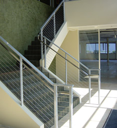
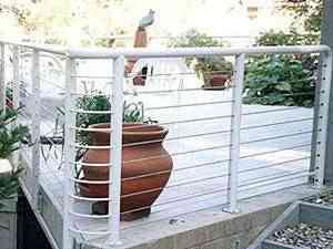
This section will address the problems encountered while designing a horizontally run cable railing system.
A horizontally run series of cables used as in-fill up in a railing is legal in most jurisdictions. A few places, however, do non permit the "ladder effect" of horizontal in-fill up elements. Therefore, the first pace to be taken is to determine if the jurisdiction of the site will permit a "ladder effect" type of railing. If horizontal railing is not allowed, we offering a vertical cable railing arrangement, which is described later on in this department.
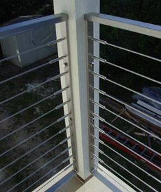
Spacing the intermediate members, which are posts and/or braces: These posts / braces will support the cable every bit it passes through the walls of the railing frame. (An intermediate post runs from the top runway to the mounting surface. A brace is a lighter weight material placed between posts, its primary purpose existence to support the cable.) Cable tin can be run quite long distances between terminating ends (150 ft. or more than, depending upon railing configuration), but volition need to exist supported at intervals betwixt finish posts, to avoid cable deflection in excess of that permitted past building codes. When a rigid cable construction is used, such as 1x19, the spacing betwixt posts and/or braces should not exceed 42".
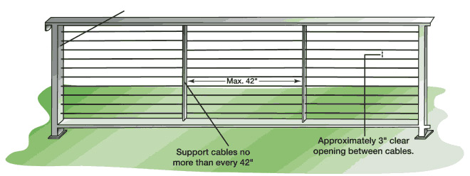
Spacing of the cables vertically is critical to minimize deflection of the cables under a vertical load. The recommended vertical spacing is approximately 3" free opening between cables when they are installed.
 | Tension of the cables and the construction of posts to which mounting and tensioning hardware is attached: deflection of the end posts must be minimized, and this is where nosotros accept found the most mistakes fabricated in the design of the railing framework. An incredible amount of tension is generated on an end post when you take 10 or more lines, each tensioned at 200 lbs. or more than over a height of 36" to 42". Frequently, designers and fabricators inexperienced in cable railings will not recognize the amount of the tension applied to the posts. The end result all too frequently is finish posts which volition curve considerably as the cables are beingness tensioned, or with a railing where the cables cannot be properly tensioned without an unacceptable amount of mail service deflection. The posts to which hardware is mounted must be constructed so that they will not deflect perceptively as the cables are tensioned to loads of 200 lbs. or more. |
All of these variables work together to minimize the deflection of the cablevision so as to non allow a 4" sphere to pass between the cables when they are properly tensioned in a well-designed frame.
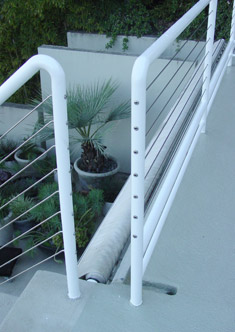
 | Bug encountered in designing a railing using vertically run cables as in-fill. Top and bottom rails are necessary in a vertical railing using cablevision, because mounting and tensioning hardware is attached to top and bottom rails instead of end posts. Schedule 80 pipage or 2"x2"x1/4" square tubing for both the top and bottom rail is recommended, because of the forces applied when the cables are properly tensioned. All the same, the amount of strength that tin be applied to a vertical cable is more often than not less than can be applied to a horizontally run cable. The result is less strength being applied to the mounting and tensioning fittings. Therefore, you may consider using 1/8" diameter cable with a vertical system, where you lot may not want to use it in a horizontal system. |
2"x i"x .120" or 3"10 1"x .120" structural steel posts with stainless steel spacers
2"10 1" or 3"10 1" tiptop and lesser rails and intermediate posts (if applicable)
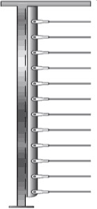
 | Frame components tin exist carbon steel or stainless steel. This style has been designed to perform satisfactorily when subjected to the tension encountered when multiple load points (cables) are attached and tensioned properly to your end posts (200 lbs. or more per line). Detailed downloadable drawings (see afterwards in this document) show proper spacing of the cables vertically on the end posts that allow for cable flex within allowable limits to meet code requirements that a 4" ball shall non pass through at any point. This railing way uses an stop postal service with ii vertical members separated by stainless steel spacers. Intermediate posts are just 1" thick. This structure is stiff withal its elements are relatively sparse, so in that location is little visual obstruction created by the frame. Notation the tubed corner sections that are illustrated. They supplant corner posts with hardware mounted on two sides or ii posts with cable pulled between them. The cable runs through tubes welded to two posts. It makes a squeamish looking corner with uniform curves going around the corner. Meet Tubed Corner Sections detailed drawings. |
ii"10 2"x .250" wall structural steel end postal service structure
2"x1" pinnacle rail and bottom rail (if applicable)
 | Frame components tin can exist carbon steel or stainless steel. This style has been designed to perform satisfactorily. When subjected to the tension encountered when multiple load points (cables) are attached and tensioned properly to your cease posts (200 lbs. or more per line). Detailed downloadable drawings (see later in this document) show proper spacing of the cables vertically on the end posts that let for cable flex inside allowable limits to encounter code requirements that a 4" ball shall non pass through at any point. Even though the end posts are ii"x2"10.250", intermediate posts tin can exist two"x1"x.120" to minimize the bulkiness of the frame. |
 | Frame components tin be carbon steel or stainless steel. This style has been designed to perform satisfactorily when subjected to the tension encountered when multiple load points (cables) are attached and tensioned properly to your end posts (200 lbs. or more than per line). Detailed downloadable drawings for one-1/four", 1-1/2" and ii" standard pipe are available. Minimum schedule 80 pipage is required for your end posts. The drawings evidence proper spacing of the cables vertically on the end posts for standard round pipe. Those spacing allow for cable flex within allowable limits to meet code requirements that a four" brawl shall not pass through at any point. Circular tubing can be used with a wall thickness at to the lowest degree comparable to schedule 80 pipage. If you are using circular tubing, the downloadable drawings must be modified to allow for the different diameters of tubing versus pipe. Annotation the tubed corner sections that are illustrated. They replace corner posts with hardware mounted on two sides or 2 posts with cablevision pulled between them. The cable runs through tubes welded to two posts. Information technology makes a squeamish looking corner with uniform curves going around the corner. See Tubed Corner Sections for detailed drawings. |
| | Frame components other than those shown in this guide can exist used using carbon steel or stainless steel. Other frame styles should exist engineered to perform satisfactorily when subjected to the tension encountered when multiple load points (cables) are attached and tensioned properly to your finish posts (200 lbs. or more per line). Center-to-center spacing of the cables vertically is critical to allow for cable flex within allowable limits to run across code requirements that a four" sphere shall not pass through at any point. |
 | Frame components tin be carbon steel or stainless steel. These styles take been designed to perform satisfactorily when subjected to the tension encountered when multiple load points (cables) are attached and tensioned properly to your stop posts (200 lbs. or more per line). Detailed downloadable drawings show proper spacing of the cables vertically on the end posts that allow for cable flex within allowable limits to meet code requirements that a 4" sphere shall not pass through at any point.
|
 | Tubed corner sections can replace corner posts with hardware mounted on 2 sides or ii posts with cable pulled between them. The cable runs through tubes welded to two posts. Information technology makes a nice looking corner with uniform curves going around the corner. Detailed downloadable drawings are available and tin can exist used or modify for your projection. Frame components can exist carbon steel or stainless steel, and your vertical posts tin exist the aforementioned textile used for your intermediate posts. |
NOTE: We strongly recommend stainless steel for exterior applications.
* Annotation: Minimum Wall thickness shown is for double finish postal service construction using two rectangular posts separated by stainless steel spacers. We do not recommend .120" wall for a stand up-alone end post. | ||||||||||||||||||||||||||||
* Note: For tubing, use wall thickness approximating wall thickness of pipe schedule shown. | ||||||||||||||||||||||||||||
| See the list of CAD drawings that tin be downloaded for engineered tubular steel and pipe railings together with cloth specifications for each railing. The fabric specifications higher up are intended as full general guidelines for use in designing a railing for which drawings are not available on the spider web site. The design professional person is responsible for engineering the railing to run into building code requirements. | ||||||||||||||||||||||||||||
| ||||||||||||||||||||||||||||
| Stainless Steel Spacers for Double End Mail Railing Construction
Stainless Steel Spacers For Use With Invisiware Fixed Tabs
| ||||||||||||||||||||||||||||
| Corner Department Tubing For use in 90° corners using tubing in the corner sections through which the cable passes. *See Note.
| ||||||||||||||||||||||||||||
| Double Terminate Post Construction With Stainless Steel Spacers Between Vertical Elements | ||
| | 3" 10 1" or 2" x 1" ten 36-1/2" high rectangular tubing with bottom track | |
| | three" x 1" or ii" 10 i" ten 36-1/2" high rectangular tubing without bottom rail | |
| | 3" x 1" or 2" 10 1" 10 42-1/2" high rectangular tubing with bottom rail | |
| | 3" ten 1" or 2" 10 1" x 42-1/two" loftier rectangular tubing without bottom rail | |
| ii" Square Structural Tubing construction (may besides be used for other sizes of square tubing) | ||
| | 2" foursquare tube ten 36-1/2" high with bottom rail | |
| | 2" square tube x 36-one/2" high without bottom runway | |
| | 2" foursquare tube x 42-1/2" loftier with lesser rail | |
| | two" foursquare tube x 42-1/two" high without bottom rail | |
| Circular Pipe (aforementioned drawings can exist used for round steel tubing of the same outside dimensions as pipe) | ||
| | 1-1/four" pipe ten 36-ane/ii" high with bottom rail | |
| | i-one/4" pipe ten 36-1/two" high without lesser track | |
| | 1-1/4" pipe x 42-ane/2" high with bottom rail | |
| | i-one/iv" pipe 10 42-1/2" loftier without bottom runway | |
| | one-1/2" pipe 10 36-i/2" high with bottom rails | |
| | 1-1/2" piping x 36-1/2" high without bottom runway | |
| | one-1/2" pipage x 42-i/2" loftier with bottom rails | |
| | ane-1/2" pipe x 42-1/ii" high without bottom rail | |
| | 2" pipage x 36-1/2" high with bottom rail | |
| | 2" pipage 10 36-1/2" high without bottom runway | |
| | ii" pipe 10 42-i/2" high with bottom track | |
| | 2" pipe x 42-1/2" high without lesser runway | |
| End Posts Using Structural Tees | ||
| | Square or rectangular tube track end options | |
| | Pipage rail finish options | |
| Tubed Corner Sections | ||
| | Floor plate | |
| | Square tubing, end or intermediate post - concrete embedding | |
| | Pipe or circular tubing, end or intermediate post - physical embedding | |
| | 3" ten 1" or 2" x 1" double end post - physical embedding | |
| | Intermediate post - concrete embedding | |
| | Steel post - fascia mounting | |
| | Forest 1-one/2" post - fascia mounting | |
| Stair Runway Terminate Posts | ||
| | Square or rectangular tube rail end options | |
| | Pipe runway end options | |
| Mounting Options | ||
| | Floor plate | |
| | Square tubing, finish or intermediate post - physical embedding | |
| | Pipe or round tubing, end or intermediate mail service - concrete embedding | |
| | iii" x 1" or two" ten 1" double end post - concrete embedding | |
| | Intermediate post - physical embedding | |
| | Steel postal service - fascia mounting | |
| | Wood 1-ane/2" post - fascia mounting | |
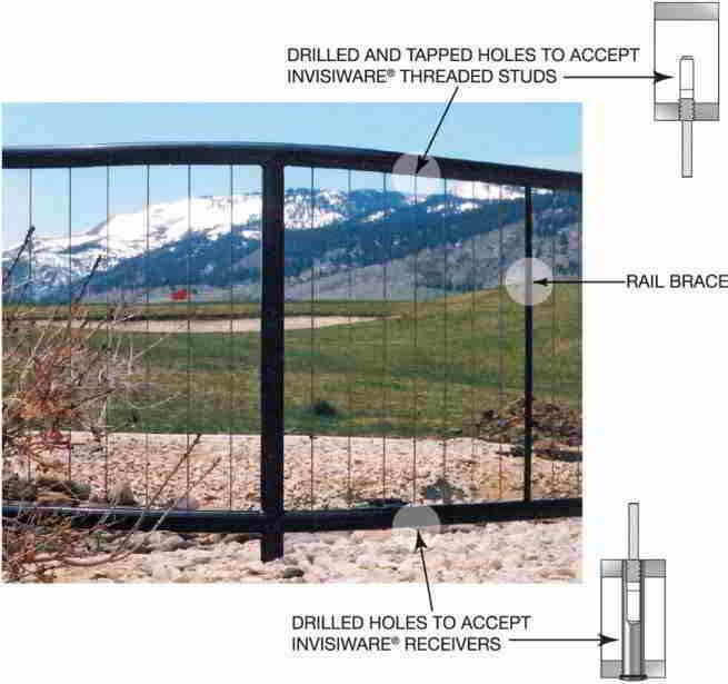
This cable railing frame manner facilitates the use of cables in the vertical position, running from the top runway to the bottom track.
Drawings afterward in this document illustrate fabricating the railing from pipage. Square or rectangular tubing can also be used, but nosotros recommend a minimum wall thickness of 1/4" in your frame material.
An Invisiware® Threaded Stud on ane stop of the cablevision is screwed into a drilled and tapped pigsty in the underside of the acme rails. An Invisiware® receiver is inserted into a hole drilled through the bottom runway. A threaded stud on the other finish of the cable is inserted into the receiver, and the cablevision is tensioned by turning the receiver with an Allen wrench.
Because the Invisiware® receiver goes all the way through a hole in the lower rails, a stainless steel frame must be used in outside applications, to prevent rust in the frame.
This style has been designed to perform satisfactorily when subjected to the tension encountered when multiple load points (cables) are fastened and tensioned properly on the top and bottom runway (200 lbs. or more than per line). Detailed downloadable drawings show proper spacing of the cables horizontally on the top and bottom posts to allow for cable flex within allowable limits to encounter most code requirements (that a 4" sphere shall not pass through at any signal). Note that nosotros recommend special rail braces to replace every 8th cable, to continue the pinnacle and lesser rail from angle when the cables are tensioned.
Note: For outside applications, specify stainless steel to prevent rust in the railing frame.
Carbon or Stainless Steel Structural Tubing
| |||||||||||||||||
| Runway Braces For use in identify of a cable at least every 8th cable on iii.25" centers between structural posts to support top and bottom track under tension.
| |||||||||||||||||
| | 1-1/4" Pipe x 36-1/2" high | |
| | 1-1/4" Piping x 42-1/2" high | |
| | 1-1/2" Pipe x 36-i/2" high | |
| | 1-ane/2" Pipe x 42-i/2" high | |
| | two" Pipe 10 36-1/2" high | |
| | 2" Pipe x 42-1/ii" high | |
| | Corner section | |
| | Corner department programme view for one-1/iv" pipe | |
| | Corner department plan view for 1-1/two" pipage | |
| | Corner department program view for 2" pipe | |
0 Response to "3/8 Stainless Steel Cable Hardware Components"
Post a Comment